

 English
 Türk
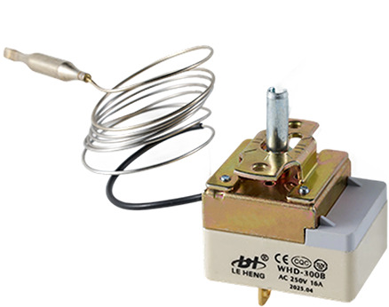
TürkWHD-E copper adjustable copper capillary thermostat is a mechanical temperature regulating devic...
Manual Reset Limit Thermostat Wiring and Reset Button Operation Explained
Understanding how to connect a Manual Reset Limit Thermostat and how its reset button functions is valuable for installers and maintenance technicians. Proper wiring ensures the device interrupts power correctly during an over‑temperature event. The reset button mechanism, meanwhile, determines how the device returns to service.
Typical Wiring Arrangement
A Manual Reset Limit Thermostat is normally installed in series with the load that controls the heating source. In a simple circuit, power flows from the supply through the limit switch, then through a contactor coil or directly to the heater, and back to the supply. The limit switch contacts are closed during normal temperatures. When the temperature rises to the limit setting, the contacts open, removing power from the heater. Because the switch is in series, no alternative path allows the heater to remain on.
Most manual reset limit devices have two terminals, though some have four terminals (two for line, two for load, allowing daisy‑chaining). The terminals are not usually polarized, meaning either wire can go to either terminal. However, for safety, the supply wire should connect to the terminal that leads to the fixed contact inside the switch. The load wire connects to the moving contact. This arrangement is not critical for function but follows good practice.
Reset Button Operation: Mechanical and Electrical View
Inside the housing, a bimetal disc or a snap‑action disc responds to temperature. When heated to the calibration point, the disc snaps, pushing a plunger that forces the contacts apart. The reset button is attached to a mechanism that holds the contacts open after the disc cools. Unlike a simple auto‑reset device, the manual reset version includes a latch. The latch keeps the contacts separated even when the bimetal returns to its room‑temperature shape.
Pressing the reset button releases the latch. A spring then pushes the contacts back together. The click heard during reset is the sound of the contacts closing and the latch re‑engaging in its ready position. If the temperature is still above the safe threshold, the disc may immediately snap again, opening the contacts. This is why cooling is necessary before a reset will hold.
Wiring Precautions
Before handling any wiring, disconnect all power to the equipment. Confirm with a voltmeter that no voltage is present. Use wire gauges appropriate for the circuit’s current rating. The limit device’s terminals are typically marked with a current and voltage rating; do not exceed those values. Use ring or spade terminals for secure connections, and tighten screws to the torque specified in the device documentation.
Do not wire the limit switch in parallel with other components. A parallel path would allow current to bypass the switch, defeating its safety function. Also, avoid connecting the reset button to any external control system as a signal input unless the device is specifically designed for that purpose. The button is purely mechanical for resetting the internal latch.
Common Wiring Errors
One frequent mistake is confusing a manual reset limit with a normally open device. Verify that the switch is closed at room temperature using a continuity test. Another error is installing the limit switch on the neutral side of a line‑voltage circuit. While this still interrupts current, it leaves the heater element energized even when the limit is open, creating a shock hazard. Always switch the ungrounded (hot) conductor.
Testing After Wiring
After completing the wiring, perform a functional test. With the system running, artificially raise the temperature near the sensor (for example, by directing warm air with a heat gun) while monitoring the heater’s power. The limit should open and shut off the heater. Allow the sensor to cool, then press the reset button. The heater should restart. This test confirms both the wiring and the reset mechanism.
A correctly wired Manual Reset Limit Thermostat provides years of reliable service. The reset button, though simple in appearance, incorporates a latch mechanism that is fundamental to the device’s safety role. Respecting its wiring requirements ensures that the device protects both equipment and people.
OUR PRODUCTS
Recommended Products
-

 WHD-E-CU Copper Adjustable Capillary Temperature Controller
 -
 Stainless Steel Adjustable Capillary Temperature Controller
The stainless steel adjustable capillary thermostat is a mechanical temperature regulating devic...
-
 Adjustable Temperature Mechanical Capillary Thermostat") WHD-B(16A/25A) Adjustable Temperature Mechanical Capillary Thermostat
WHD-B(16A/25A) Adjustable Temperature Mechanical Capillary ThermostatWHD-B(16A/25A) Adjustable Temperature Mechanical Capillary Thermostat is specially designed for ...
-
 WHD-RQ400-BY Digital Display Thermostatic Controller
The WHD-RQ400-BY digital thermostat is an intelligent control device designed specifically for h...
-
 WHD-H2 320 Degree Oven Heating Temperature Limiter
The WHD-H2 oven heating limiter is designed for precise temperature control, with a maximum limi...
-
 WHD-D Adjustable Mechanical Temperature Thermostat
The WHD-D adjustable mechanical thermostat offers reliable temperature control. It features a ma...
-
 WHD-YL260 Oil Furnace Digital Thermostat
The WHD-YL260 oil furnace thermostat is an intelligent temperature control device designed speci...
-
 WHD-EM Limit Temperature Controller
The WHD-EM limit temperature controller is a highly reliable device for critical temperature mon...
PLEASE LEAVE YOUR SPECIFIC REQUIREMENT
QUICK LINKS
PRODUCTS
CONTACT
-
+86-15957748531
+86-15558959105
+86-19588099846
+86-18815077137 -
jilly@wzleh.com
east@wzleh.com
scott@wzleh.com
kim@wzleh.com
ADDRESS
- STI Park #B-2, Hongqiao Yueqing City, Zhejiang, China, 325608


Leheng Thermostat Factory
Copyright © Wenzhou Leheng Technology Co., Ltd. All Rights Reserved.